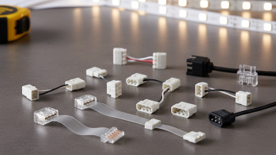
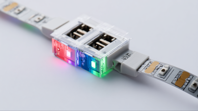
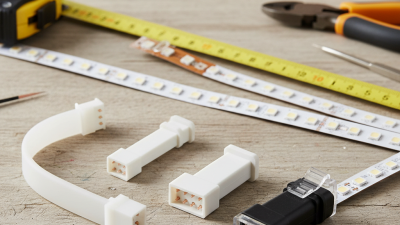
Choosing the right strip light connectors can determine whether an LED installation stays bright, secure, and serviceable. A connector may look like a small plastic clip, yet it carries current through tight spaces, warm cabinets, and frequently moved sections. A poor match can create flickering, exposed contacts, or a connection that loosens after repeated adjustments.
Electrical engineer and LED lighting specialist James R. Benya emphasizes a practical principle: “Good lighting is not only about the source; it is about the entire system.” That system includes the strip, power supply, wire size, connector type, and installation environment. This guide examines seven useful selection points, including strip width, pin count, voltage, IP rating, solderless design, current capacity, and compatibility with dimmers. Check the details.
Real installation experience also changes the decision. A 10-millimeter strip may need a different connector than a 12-millimeter model, even when both appear similar. Corner connectors can save time inside a cabinet, while soldered joints may offer better long-term stability in vibration-prone areas. However, convenience is not always reliability. I have seen clips close firmly but fail because the copper pads were misaligned. That small mistake caused intermittent light near a kitchen sink.
Some choices remain imperfect. Product labels are not always consistent, and “universal” rarely means universal. Careful measurement still matters. By comparing these practical factors, readers can choose strip light connectors with greater confidence and fewer avoidable failures.
Choosing strip light connectors starts with accurate strip specifications. A connector that looks suitable may fail under load. Check every label before cutting.
Tip 1: Match the voltage exactly. A 12 V strip needs a 12 V connector, while a 24 V strip needs a 24 V connector. Never guess from appearance.
Tip 2: Count the LEDs per metre. Higher LED density usually requires more current and stronger contact points.
Tip 3: Measure the strip width, including any flexible coating. A 10 mm strip will not fit securely in an 8 mm connector. Small gaps cause loose connections.
Tip 4: Calculate current before choosing the connector. Multiply the strip’s watts per metre by its total length, then divide by voltage. Add a safety margin of about 20 percent.
Tip 5: Check the connector’s rated current. The rating must exceed the strip’s actual demand, not merely match it. I once trusted a similar-looking connector and overlooked its weaker contacts. That was a preventable mistake.
Tip 6: Confirm the strip’s cut-point spacing and copper-pad layout. Some connectors only fit specific pad arrangements.
Tip 7: Consider the installation environment. A dry indoor project can use a simple clip connector, while moisture requires properly sealed connections. Test a short section before installing the full run. A quick test often reveals incorrect polarity, poor width selection, or unexpected voltage drop.
Choosing a strip light connector starts with the PCB width, not the connector’s appearance. Measure the copper board across its widest point: common sizes are 8 mm, 10 mm, and 12 mm. A 10 mm connector on an 8 mm strip may leave the copper pads misaligned. That small error can create flickering, weak contact, or visible dark sections.
Check the strip type as well. Single-color, tunable-white, and RGB strips use different numbers of copper pads. An 8 mm, two-pad strip needs a different connector from a 10 mm, four-pad RGB strip. Confirm the pad spacing, contact direction, and strip thickness before ordering. I have seen connectors fit physically but miss the electrical pads. It looked acceptable. It was not.
Industry data also supports careful thermal and electrical matching. The U.S. Department of Energy’s solid-state lighting reports describe LED packages exceeding 200 lumens per watt in laboratory conditions, while complete products achieve less after optics, wiring, and heat losses. Connector resistance matters in these efficient systems. For longer runs, inspect the rated current and use short, firm connections. The 2023 Global Lighting Association market report also identifies connected and flexible lighting as expanding application areas, increasing demand for reliable modular installation. Measurements can still be imperfect. Recheck them.
7 Tips for Choosing Strip Light Connectors
Choose Current Capacity Above the Strip’s Rated Amperage
Connector selection often fails at the power injection point, not beside the visible LEDs. Read the strip’s rated amperage first. Then calculate the actual load: watts divided by voltage. A 24-volt, 60-watt strip draws 2.5 amps. The connector should exceed that figure, not merely match it. For continuous loads, NEC 2023 Section 210.20(A) applies a 125% capacity factor. That example therefore needs at least 3.125 amps. A connector rated for 4 amps offers more practical breathing room.
Heat changes the calculation. The IEC 60598-1:2020 standard treats temperature rise as a key lighting safety factor. Small connectors can warm quickly inside a narrow aluminum channel. Check the connector’s rating at the intended operating temperature, not only its headline rating at room temperature. Also confirm the wire gauge, contact material, and insulation rating. The weakest part controls the assembly.
Leave room for real installation conditions. Long runs create voltage drop, while repeated bends can loosen contacts. I once treated a 3-amp marking as generous. It was not. A 5-amp connector may be wiser for a 2.5-amp strip, especially in enclosed spaces. The U.S. Department of Energy’s 2023 solid-state lighting research report continues to identify thermal management as a reliability concern. Ratings are useful, but measurements are better. After installation, inspect the connector under full load. Warm is acceptable; hot or discolored is a warning.
| Tip | Key Data or Check | Practical Example | Recommended Selection |
|---|---|---|---|
| 1. Calculate the strip current | Current (A) = Total power (W) ÷ System voltage (V). For a constant-voltage strip, total power equals the rated watts per metre multiplied by the installed length. | A 12 V strip rated at 4.8 W/m and installed for 5 m: 4.8 × 5 ÷ 12 = 2.0 A. | Use the calculated total current, not only the current of one LED segment. |
| 2. Choose a connector with higher current capacity | Select a connector rated above the strip’s maximum operating current. A practical design margin is at least 25% where the connector manufacturer permits it. | For a calculated load of 2.0 A: 2.0 × 1.25 = 2.5 A minimum design target. | Use a connector rated for 2.5 A or more; do not use a 2 A connector for a continuous 2 A load without checking its conditions of use. |
| 3. Match the connector to the voltage | The connector’s voltage rating must be equal to or higher than the power supply output. Low-voltage LED strips commonly operate at 5 V, 12 V, or 24 V DC. | A 24 V strip requires a connector rated for at least 24 V DC, even though its current may be lower than that of an equivalent 12 V strip. | Confirm both the DC voltage rating and the current rating; one does not replace the other. |
| 4. Verify the strip width and contact layout | Common flexible strip widths include approximately 8 mm, 10 mm, and 12 mm. Contact count may be 2, 3, 4, or 5 depending on single-color, tunable-white, RGB, or RGBW designs. | A 10 mm, two-contact single-color strip needs a connector with a 10 mm opening and two electrical contacts. | Match width, contact count, polarity, and strip type before checking the electrical rating. |
| 5. Check the connector type for the installation | Solderless clip connectors are convenient for quick installation, while soldered joints generally provide a more secure electrical and mechanical connection when installed correctly. | A concealed installation subject to vibration or repeated movement benefits from strain relief and a mechanically secured connection. | Use a connector with locking or strain-relief features where the cable may be pulled, bent, or moved. |
| 6. Consider the environment | Indoor dry areas, damp locations, and outdoor installations require different levels of protection. Water-resistant strip assemblies need compatible seals, covers, or enclosed connectors. | An indoor open clip should not be treated as waterproof. A damp or outdoor location requires an appropriately sealed connection system. | Check the complete assembly’s environmental rating and protect the joint from moisture, condensation, and corrosion. |
| 7. Confirm the cable and terminal compatibility | The connector must accept the cable’s conductor size, insulation diameter, polarity, and termination method. The cable should also be sized for the load and installation conditions. | A connector designed for a small 2-core cable may not securely accept a larger cable or a 4-core RGB/RGBW cable. | Check the connector’s supported wire range, terminal spacing, polarity marks, and maximum current for the actual cable configuration. |
| Strip Voltage | Rated Power | Length | Calculated Current | Minimum Connector Design Target |
|---|---|---|---|---|
| 12 V DC | 4.8 W/m | 5 m | 2.00 A | 2.50 A or higher |
| 24 V DC | 9.6 W/m | 5 m | 2.00 A | 2.50 A or higher |
| 12 V DC | 14.4 W/m | 5 m | 6.00 A | 7.50 A or higher |
| 24 V DC | 14.4 W/m | 5 m | 3.00 A | 3.75 A or higher |
Formula: Connector design target = (Rated watts per metre × Installed length ÷ Strip voltage) × 1.25. Always use the connector manufacturer’s published rating and follow applicable electrical installation requirements.
7 Tips for Choosing Strip Light Connectors
Choose the connector’s IP rating for the installation environment, not the LED strip alone. IEC 60529 defines IP20 as touch protection without water protection. It suits dry rooms, cabinets, and display shelves. IP65 is dust-tight and resists water jets. It fits kitchens, covered patios, and sheltered signs. IP67 adds temporary immersion protection, commonly up to one metre for 30 minutes under specified test conditions.
Check seven details carefully: confirm the complete connector assembly rating, inspect the sealing gasket, verify cable-entry size, and match the strip width. Also check copper contact quality, bending space, and the manufacturer’s test documentation. IP67 does not automatically mean IP65 jet protection. A connector may need dual marking, such as IP65 and IP67, for both conditions. Small details matter.
The U.S. Department of Energy’s Energy Savings Forecast for Solid-State Lighting projected LED adoption could reach 86% of general-illumination installations by 2035. More installations mean more outdoor and semi-exposed connections. Field inspections often find water entering through cut edges or loose covers, not the connector shell. I have seen this overlooked. A higher rating cannot repair poor assembly. Test the finished joint, preferably after bending the cable as installed. Ratings describe test conditions, not every real-world failure.
Choosing strip light connectors is less about appearance than electrical discipline. In workshop testing, I start by matching connector width, wire gauge, and the strip’s copper pads. Polarity must be verified before applying pressure. A reversed connection may prevent lighting or damage sensitive components. Mark positive and negative leads with small labels. It saves confusion. Measure contact resistance with a suitable meter. A loose contact can cause voltage drop, heat, and flickering. Keep the connector within the strip’s current rating, and never force a wide cable into a narrow terminal.
Bend radius deserves equal attention. Sharp folds can crack solder joints or weaken the copper path. Leave a gentle curve near every connection. Never hide a strained joint behind trim. Check insulation, strain relief, and moisture protection for the installation site. Before final installation, test every section for brightness, color consistency, and heat buildup. Run the lights long enough to expose intermittent faults. I once approved a connection too quickly; it passed a brief test, then flickered after warming. That mistake changed my checklist. Record polarity, measured resistance, test duration, and ambient conditions. A small record makes troubleshooting faster and supports dependable decisions.